1 - End Device Activation
This book covers LoRaWAN® end-device activation in depth.
Todo
Add more details
Over-the-Air Activation (OTAA) Device Provisioning
Step 3D: End Device Handles Join Accept
If the join server processed the Join Request successfully, the end device should then receive the encrypted Join Accept response frame.
Decrypt the Encrypted Field
The encrypted field containing all the Join Accept fields and the MIC is found within the PHY Payload in the LoRaWAN® packet, as shown in Figure 1.
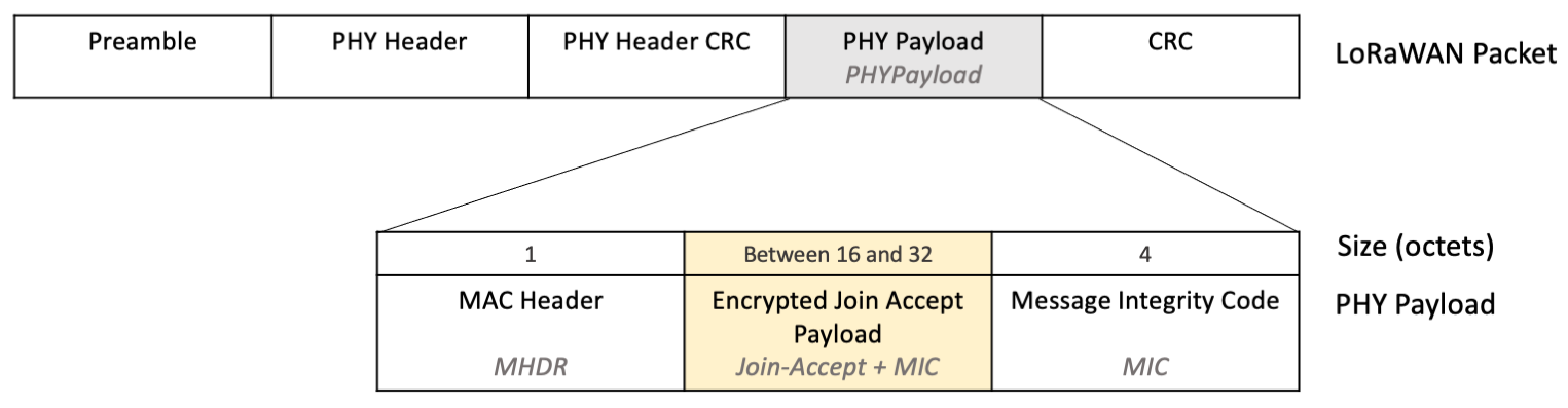
Figure 1: Join-Accept and MIC encrypted, shown within the PHY Payload in the LoRaWAN Packet
Note
The exact size of the encrypted payload depends on whether there were any network parameters (CFList) supplied in the Join Accept. Since the MHDR length is fixed at 1 octet, and the MIC length is fixed at 4 octets, you decrypt all the remaining octets between the first octet and the final 4 octets.
Decrypt the octets containing the encrypted payload using the AES encrypt function, which is applied in Electronic Code Book (ECB) mode, with the AppKey as the secret.
Warning
The encrypted Join Accept frame must be decrypted using the AES encrypt function in ECB mode, and not the AES decrypt function. This avoids having the end device implement both AES encryption and decryption.
The fields returned after decryption, as shown in Figure 2, are the join server nonce (JoinNonce), join server network identifier (NetID), end device address (DevAddr), the downlink configuration settings (DLSettings), a desired delay between transmission and opening receive windows (RXDelay), and the optional list of network parameters (CFList), as well as a repeat of the message integrity code (MIC), also found in the PHYPayload.
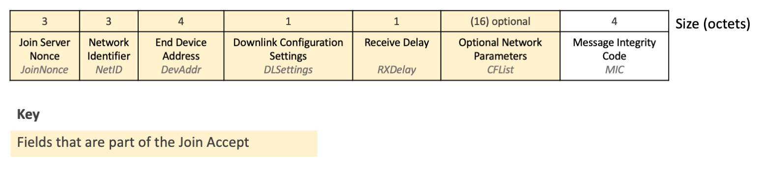
Figure 2: Fields found after decrypting the encrypted payload
Note
When dividing the decrypted output into individual fields, note that the fields up to the CFList are all fixed in length (12 octets total), and the MIC after the CFList is fixed in length (4 octets). This means the remaining octets, if any are left over, comprise the optional CFList field.
Verify the Message Integrity Code (MIC)
Calculate the message integrity code (MIC) to verify the integrity of the Join Accept message and ensure it has not been tampered with. Calculate the MIC over the Mac Header (MHDR), JoinNonce, NetId, DevAddr, DLSettings, RXDelay, and CFList using the AppKey following the instructions at line 1481 in Section 6.2.6, ‘Join-Accept frame’ (page 45) of the TS001-1.0.4 LoRaWAN® L2 1.0.4 Specification.
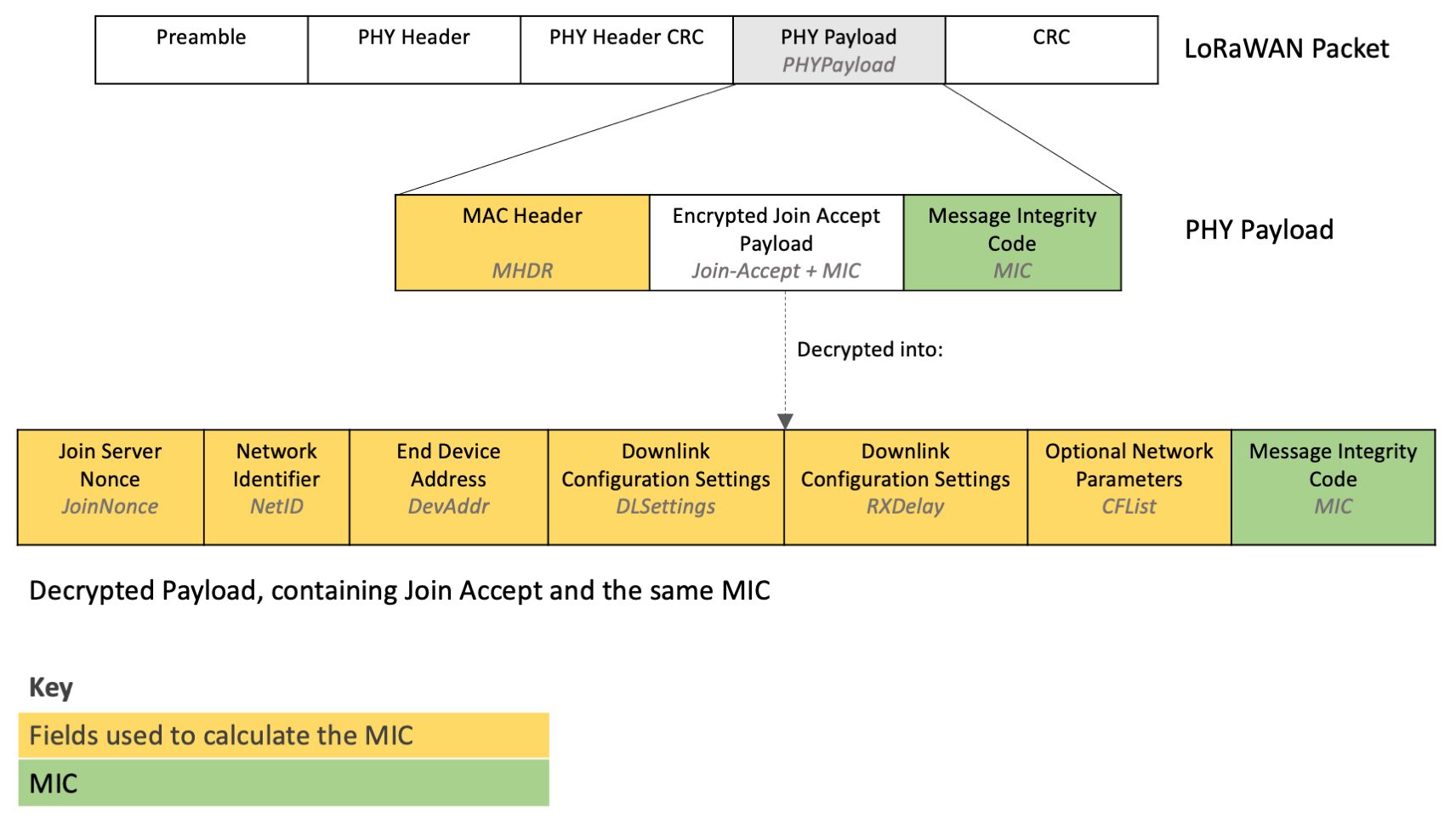
Figure 3: Fields used to calculate the MIC
Verify that the MIC you calculate matches the MIC returned in the PHY Payload, as well as the MIC found in the encrypted payload that was just decrypted. If any MIC does not match the others, ignore this message.
Check the Join Nonce to Prevent Join Accept Replay Attacks
If an adversary is within range of the end device, they can record a Join Accept message and subsequently replay it in response to a future Join Request from the device. This type of attack is known as a replay attack. If the end device accepts this replayed Join Accept, it will generate the session keys using the JoinNonce in the older Join Accept, which will be different from the Join Nonce used by the network server. As a result, the end device will generate incorrect session keys, and the network server will reject any further uplinks. This type of attack is described in more detail in the section entitled ‘Issue #1: Join-accept replays’ (page 6) of the technical recommendation document Technical Recommendations for Preventing State Synchronization Issues around LoRaWAN® 1.0.x Join Procedure.
To prevent a Join Accept replay attack, the end device could store every single JoinNonce value received in previous Join Accept messages, and reject new Join Accept messages containing a JoinNonce value that is already stored. The Join Nonces must be stored in non-volatile memory (NVM) so that they are not lost when the device is power cycled. However, to conserve memory usage, the device will need to limit the number of Join Nonces that are stored. This approach will therefore allow a replay attack if the Join Nonce used in that Join Accept is no longer being stored.
Another approach to preventing Join Accept replay attacks is for join servers to use a device-specific incrementing counter as the JoinNonce value, which increments once for each Join Accept issued. This means the JoinNonce received for each Join Accept would be 1, then 2, then 3 etc. The end device then checks that the JoinNonce in the Join Accept is higher than the previously stored JoinNonce value, ignoring the entire Join Accept if it is not. If the Join Accept is accepted, the new JoinNonce value is stored in NVM. This approach has no limitation on the number of Join Accepts that can be issued, and the end device does not need to store any Join Nonces. For more information refer to the section entitled ‘Remedy #1: Preventing Join-accept replays’ (page 8) of Technical Recommendations for Preventing State Synchronization Issues around LoRaWAN® 1.0.x Join Procedure.
Before implementing this approach, first verify that the network server or join server you use supports an incrementing Join Nonce by checking the documentation at the join server/network server or contacting your provider.
Warning
If you implement the incremental Join Nonce check on your end device, you must be aware of the following:
-
The end device can no longer be used as-is with a network server or join server that does not support an incrementing Join Nonce. To enable your end device to work with a network server or join server that does not increment its Join Nonce, program the software on the end device to allow users to disable and enable the incrementing Join Nonce behavior via a downlink. When checking for an incrementing Join Nonce is disabled, the device should be programmed to check each JoinNonce value against a list of previously received JoinNonce values.
-
After a device implementing incremental Join Nonce checks has joined a network, it cannot be moved to another network server which also supports incrementing Join Nonce’s without first resetting the last stored JoinNonce value on the end device. If this reset is not performed, the end device will reject the first Join Accept broadcast by the new network when it has a JoinNonce value lower than the last stored value. You will need to program an option that allows you to reset the last stored JoinNonce value on the device via a downlink or using a hard-wired connection.
Alternatively, you must request the network server/join server set the value of the first JoinNonce issued to be one higher than the one stored on the end device. Check if this is possible by reviewing the documentation at the network server/join server or contacting your provider.
Generate the Session Keys
You use the same algorithm as the join server used to generate the NwkSKey and AppSKey session keys. The keys are generated using the AppKey along with the JoinNonce, NetID, and DevNonce found in the decrypted Join Accept payload. Follow the instructions at lines 1479 and 1480 in Section 6.2.6, ‘Join-Accept frame’ (page 45) of the TS001-1.0.4 LoRaWAN® L2 1.0.4 Specification to generate the keys.
Note
Store the NwkSKey and AppSKey session keys in non-volatile memory (NVM) to avoid having to rejoin the network when the device is power cycled.
Store the Device Address (DevAddr)
The device address (DevAddr) found in the Join Accept is used in uplink frames sent from the end device after the activation process. Store the DevAddr in non-volatile memory (NVM) ready for use when sending uplinks.
Handle the Downlink Configuration Settings (DLSettings and RXDelay)
The downlink configuration settings field (DLSettings) contains two settings fields, the RX1DROffset and RX2DataRate fields.
-
RX1DROffset is used by the network server to adjust the data rate offset between the uplink and the first receive window (RX1).
-
RX2DataRate is used by the network server to adjust the data rate for the second receive window following an uplink (RX2).
Following the RX1DROffset and RX2DataRate initially configured in this Join Accept, these fields are updated via the Receive Windows Parameters MAC Command (RXParamSetupReq). The documentation for this command also serves as a detailed guide to these fields, found in Section 5.4, Receive Windows Parameters (page 33) of the TS001-1.0.4 LoRaWAN® L2 1.0.4 Specification.
The RXDelay field defines the delay between the end of the uplink transmission and the opening of the first receive window.
Following the RXDelay initially configured in the Join Accept, the value is updated via the Receive Window Timing MAC Command (RXTimingSetupReq) Del field. Both fields follow the same conventions. To understand the RXDelay field, read the documentation for the identically formatted Del field in Section 5.7, ‘Setting Delay between TX and RX’ (page 39) of the TS001-1.0.4 LoRaWAN® L2 1.0.4 Specification.
The data rate offset, data rate, and delay communicated by these fields must be used in all further transmissions until informed otherwise by the corresponding MAC commands (RXParamSetupReq and RXTimingSetupReq) and replace the default regional settings for these values.
Set Initial Data Rate
Set the initial data rate used for transmitting uplinks to the same data rate that was used for the transmission of the Join Request message that resulted in this Join Accept being received.
Set Initial TX Power
The end device should initially broadcast using the maximum TX Power level it can support and is permitted for the region in which it will operate, specified in the ‘Data Rate and End-device Output Power encoding’ subsection for the region in Section 2 of the RP002-1.0.4 LoRaWAN Regional Parameters specification.
Set Initial Channel Frequencies
A list of network parameters may be supplied in the CFList field. This field may indicate the channels that your end device should use. The details of these parameters and whether they will be supplied is region-specific and can be found in the ‘Join-Accept CFList’ subsection for the region in Section 2 of the RP002-1.0.4 LoRaWAN Regional Parameters specification.
If the network parameters have not been supplied, the default channel frequencies for the region the end device will operate in must be used, found in the ‘Band Channel Frequencies’ subsection for the region in Section 2 of the RP002-1.0.4 LoRaWAN Regional Parameters specification.
The device should generate a pseudo-randomly sorted list of the channels available for its region and then iterate through each channel in this list with each transmission, as described in Section 3.7, ‘Avoiding Synchronous Behavior’ (page 16) of the TR007 Developing LoRaWAN® Devices V1.0.0. This minimizes the risk of multiple end devices all broadcasting on the same channel, increasing the chance of messages reaching a gateway.
Set Initial NBTrans
The number of retransmissions (NBTrans) must be set to 1.
Note
Retransmissions are discussed in greater detail later in section Retransmitting Uplinks, of the Receiving Messages Book.
Reset the Frame Counters (FCntUp and FCntDown)
Reset the frame counters (FCntUp and FCntDown) values to 0.
The first uplink sent by the end device after activation includes FCntUp set to 0. FCntUp is incremented by 1 for all subsequent new uplink messages.
When each new downlink is received from the network server the FCntDown is incremented. If the new downlink contains an FCntDown that is lower than the FCntDown in the previous received message, the downlink is ignored.
Learn more about the frame counter in Section 4.3.1.5, ‘Frame Counter’ (page 22) of the TS001-1.0.4 LoRaWAN® L2 1.0.4 Specification.
Note
The frame counters do not need to be stored in non-volatile memory (NVM) unless power cycling your device does not trigger a rejoin. Typically, a power cycle will cause the device to rejoin the network server, which must reset the frame counters.