Stage 4: Registering Your End Node with the Network Server
Join Your Device to the Network
Click Gateways in the menu on the left.
-
Verify that your gateway has a recent date listed under Last Seen.
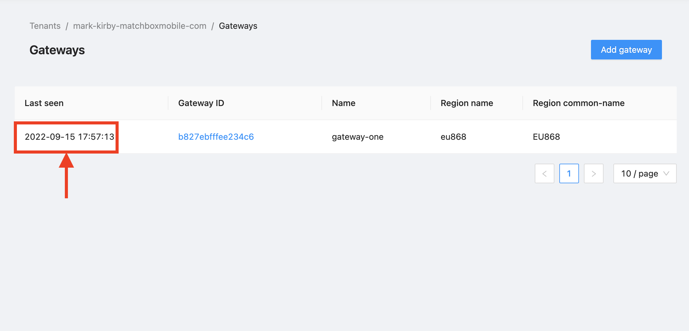
Figure 5: Gateways page showing gateway as online.
Note
If you do not see your gateway listed, or if it is offline, verify that it is turned on and recheck the steps you followed in the Register and Connect Your Gateway to the Semtech Network Server section of the Semtech Network User Guide.
-
Click Applications in the menu on the left.
-
Click the link to the application you created earlier.
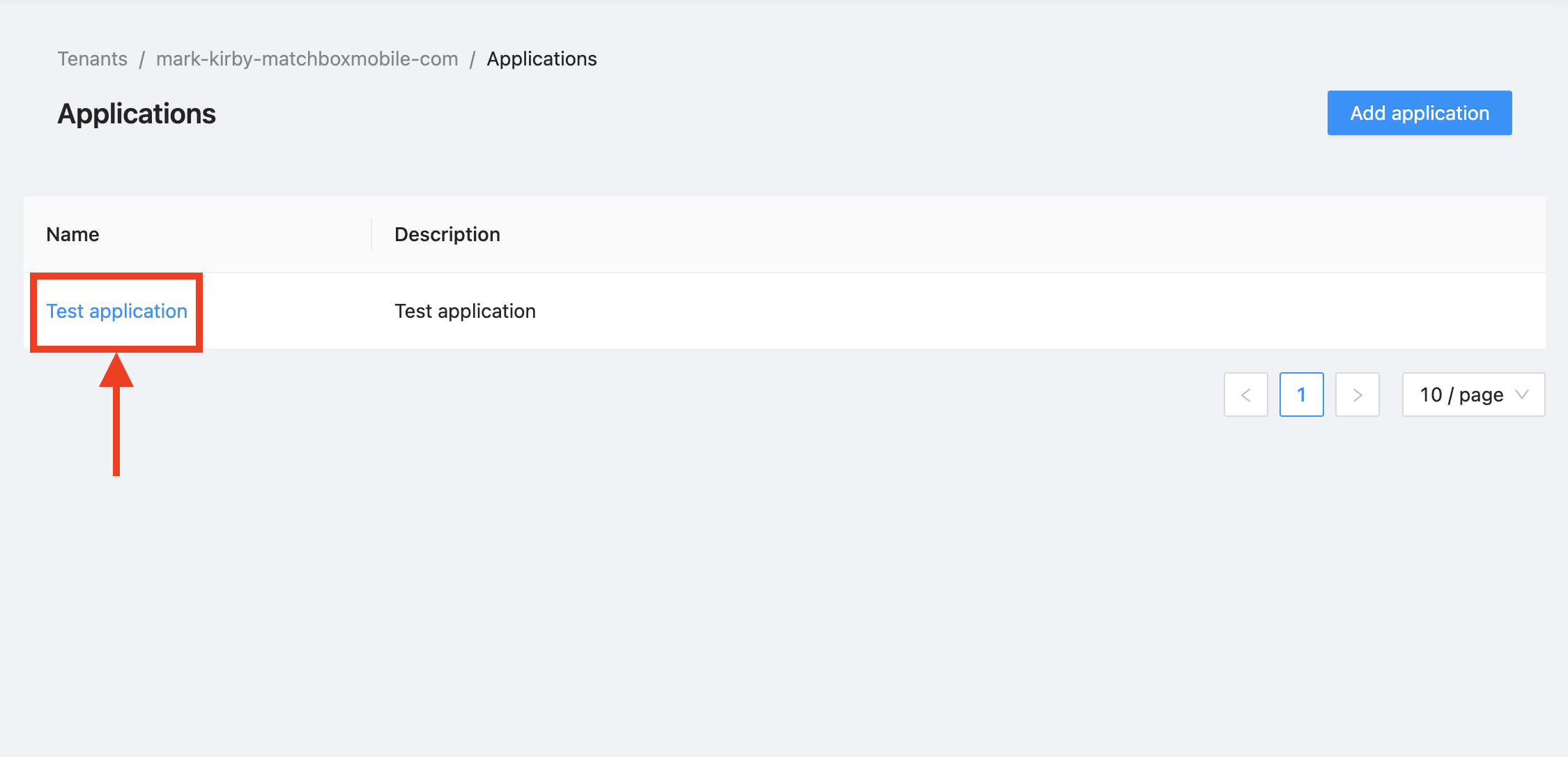
Figure 6: Link to Application
-
The devices registered to the application appear. Click the link in the DevEUI field of the device you are about to join to the network.
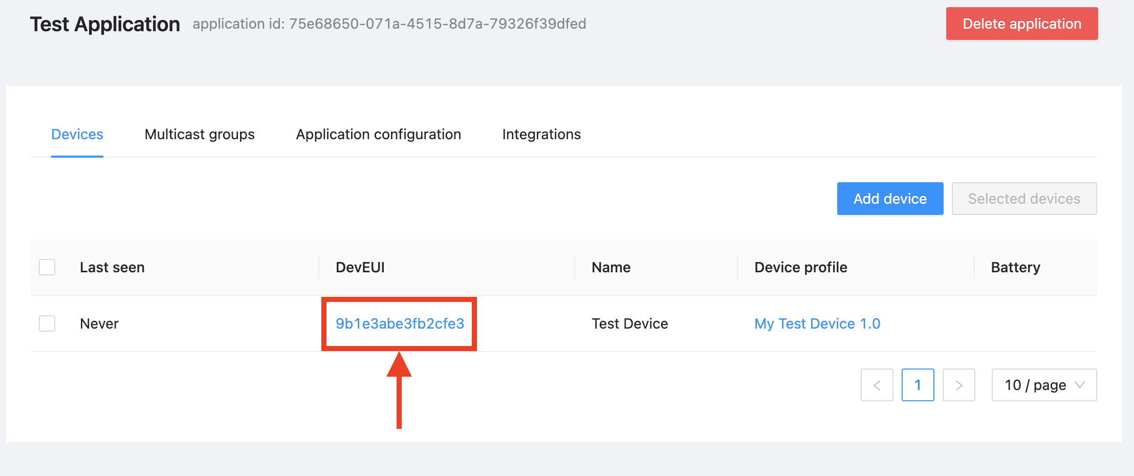
Figure 7: Link to Device
-
Select the Events tab.
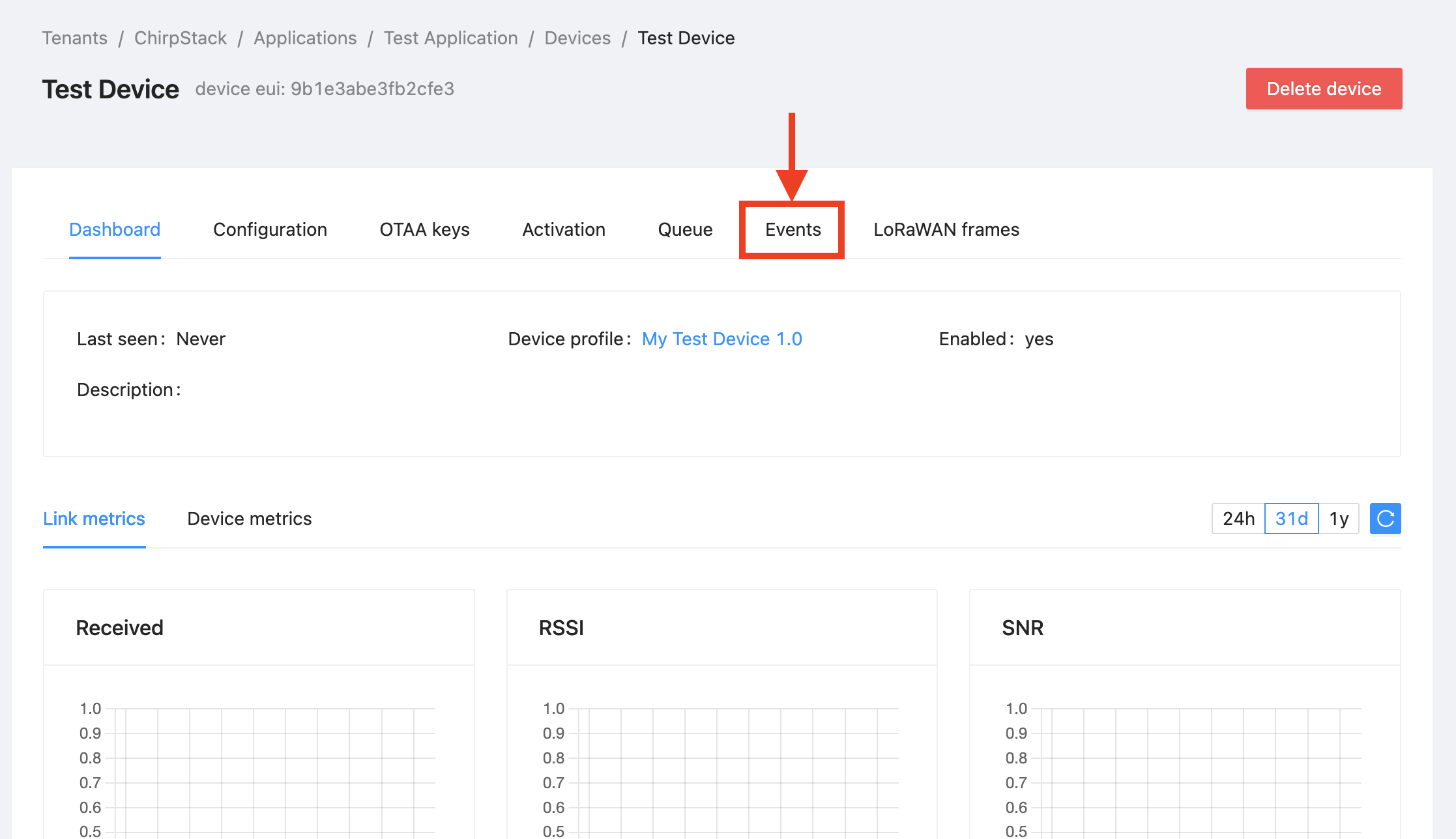
Figure 8: Events Tab in the Device Page
-
A spinning wheel displays. As events occur, they will appear here. Leave this tab open while you complete the remaining steps in this section.
Note
The last 10 events are always visible on this page, so if you accidentally close it, you can reopen it and continue to view the events.
-
Connect the Arduino board to your computer via the USB-B cable. You should see power LEDs illuminate on the Arduino and on the shield.
-
Connect the broadcasting device to the computer’s USB port using the USB-B cable. You should see a power LED illuminate on the Arduino and on the shield.
-
At the Arduino IDE menu, select Tools > Port. Select the port labeled with the model of your Arduino board.
Note
If none of the ports are labeled, disconnect the Arduino board and reopen the menu; the entry that disappears should be your board. Reconnect the board, then select the entry that had disappeared.
-
At the Arduino IDE menu, open the Serial Monitor by selecting Tools > Serial Monitor. Verify that the 9600 baud option is selected.
-
Verify and upload the sketch using the buttons in the Sketch Window menu bar.
-
The logs showing the EV_JOINING and EV_JOINED messages display in the Serial Monitor. The device has now completed the OTAA process, using the Device EUI and Application Key.
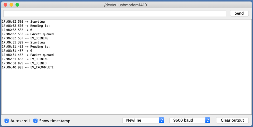
Figure 9: Serial Monitor showing the join process
Warning
If you only see the EV_JOINING message, read on to learn how to open the events tab in the Semtech Network Server and debug further.
-
The join event appears in the Events view when the OTAA process completes, as shown in Figure 10 at label A.
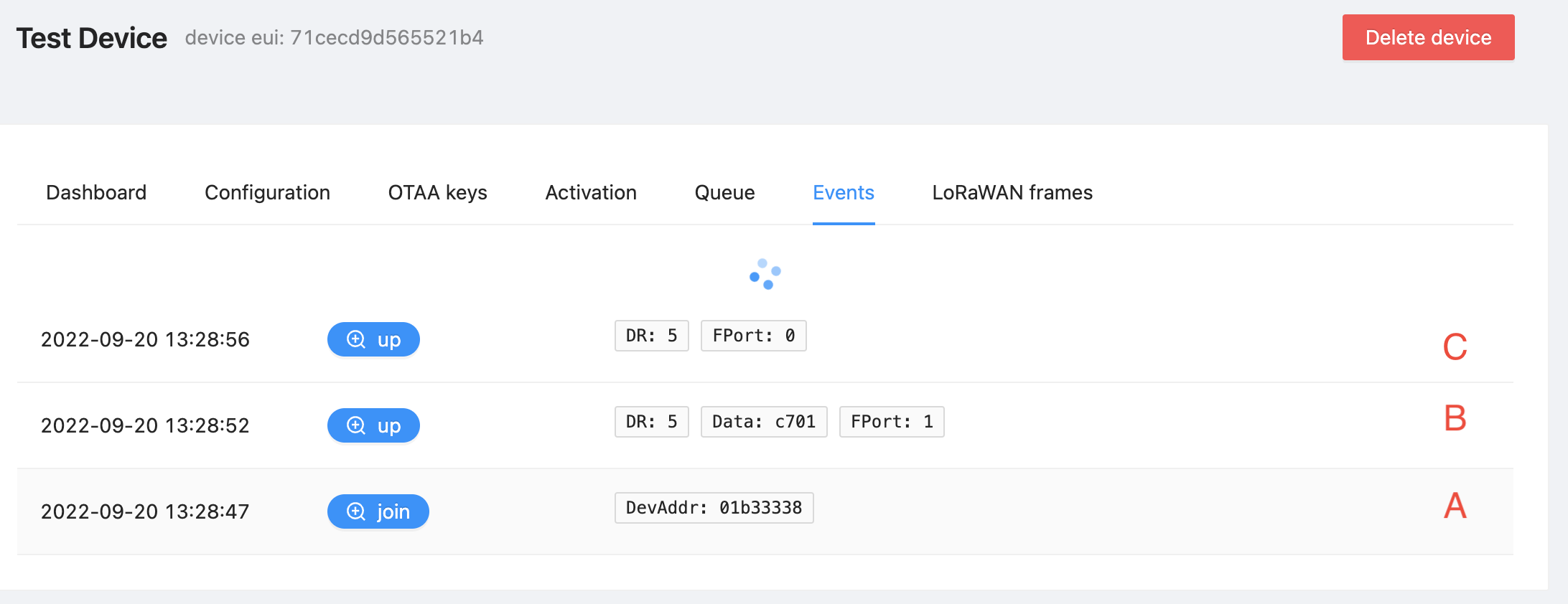
Figure 10: Events Tab Showing join (A) and up (B, C) Events
When the device sends uplinks, the up event appears, as shown in Figure 10 at B and C.
Read the ChirpStack documentation Event types page to view a list of all event types.
Warning
If no messages display, double-check that the DevEUI is correct, revisiting the section Configure the LoRaWAN® Node Moisture Sensor. If an error message displays reporting Message Integrity Code (MIC) issues, make sure that the AppKey is correct, revisiting the section Configure the LoRaWAN® Node Moisture Sensor.
-
On the same page, select the Dashboard tab, indicated in Figure 11 at A.
The Last seen field on the left shows a recent timestamp, shown in Figure 11 at B. The Enabled field on the right shows that the device is enabled, shown in Figure 11 at C.
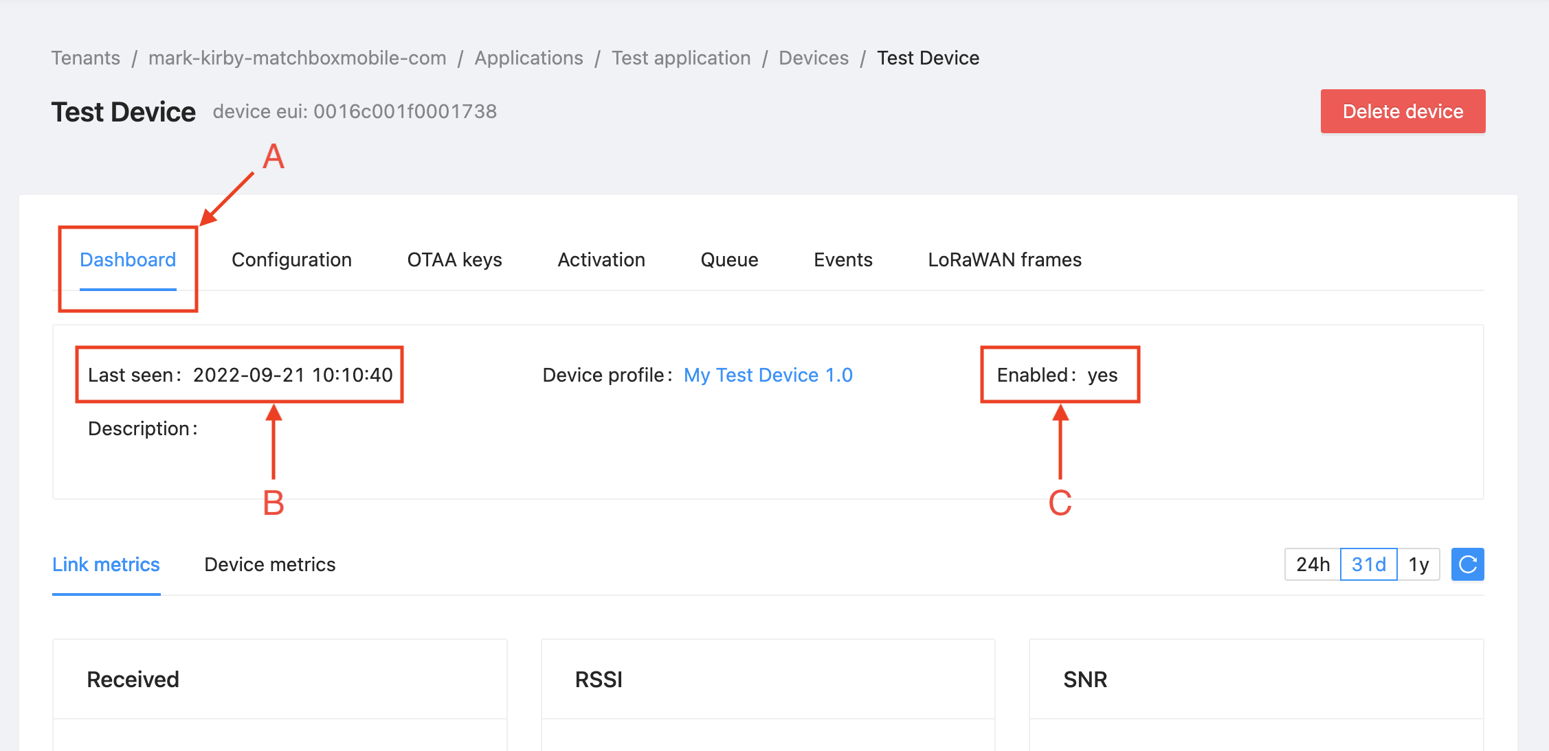
Figure 11: Dashboard Tab Showing Location of the Tab (A), Last seen Field (B), and Enabled Field (C)
-
On the same page, select the LoRaWAN frames tab. This tab shows the LoRaWAN frames sent to or from the device. Figure 12 shows the LoRaWAN frames that generated the events shown in Figure 10.
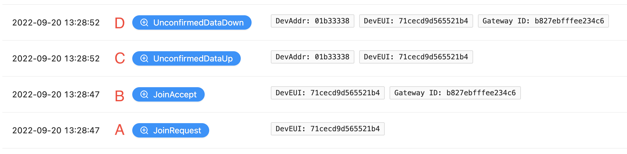
Figure 12: LoRaWAN frames Tab Showing JoinRequest (A), JoinAccept (B), UnconfirmedDataUp (C) and UnconfirmedDataDown (D) Frames
The JoinRequest frame sent from the device to the network server shown in Figure 12 at A, and the JoinAccept sent from the network server to the device shown at B, are the two frames that make up the join event shown in Figure 10.
The UnconfirmedDataUp frame sent from the device to the network server shown in Figure 12 at C creates the up event shown in Figure 10 at B.
Note
You can inspect any frame in the Details pane by clicking the magnifying glass (
 ) icon. To easily understand the contents of the Details pane, you should first learn the format of each type of frame so that you can easily identify the fields by name and understand what each means and how to interpret it.
Read the In-Depth: LoRaWAN® End Device Activation paper to learn the structure of the Join Request frame and the structure of the Join Accept frame.
Read the In-Depth: Sending and Receiving Messages with LoRaWAN® paper to learn the structure of the uplink frame and the structure of the downlink frame downlink fields.
You have now successfully joined to the network.